


Charging a LiFePO4 battery properly is essential for performance, lifespan, and safety. But with different chargers and methods, it's easy to get confused. Can you use a lead-acid charger? What's the best way to charge in parallel or series? This guide covers key charging tips, best practices, and FAQs to keep your LiFePO4 battery running at its best!
Table of Content
- Preparation Checklist for Charging a LiFePO4 Battery
- 1. Charger & Connection Check
- 2. Charging Compatibility
- 3. Charging Timing & Environment
- 4. BMS & Safety Precautions
- The Importance of Using a LiFePO4 Battery Charger
- Can I Use a Lead-Acid Charger for LiFePO4 Batteries?
- Why Is a Dedicated LiFePO4 Battery Charger the Better Choice?
- Three Best Ways to Charging a LiFePO4 Battery
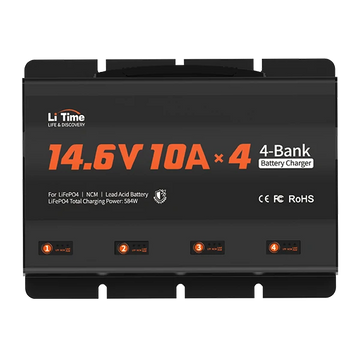
- 1. Dedicated LiFePO4 Battery Charger
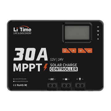
- 2. Solar System + MPPT Controller
- 3. Vehicle Alternator + DC-DC Charger
- How Long Will It Take to Charge a LiFePO4 Battery?
- FAQs on charging lifepo4 batteries
Preparation Checklist for Charging a LiFePO4 Battery
No matter the charging method (charger/solar/generator), follow these steps for safe and efficient charging:
1. Charger & Connection Check
Inspect all cables and connectors (charger, solar panel, generator) for insulation damage or wear.
Clean battery terminals and charging ports to prevent oxidation and poor contact.
Secure all connections per the battery manual to avoid loose terminals.
2. Charging Compatibility
Ensure the charger, MPPT controller, or voltage regulator supports LiFePO4 voltage ranges (12V/24V/48V).
If using solar or a generator, verify that the output parameters match the battery requirements.
3. Charging Timing & Environment
Charge at 20% SOC (80% DOD); if the BMS disconnects due to low voltage (<10V), charge immediately.
Optimal charging temperature: 0°C ~ 45°C (32°F ~ 113°F).
- Low-temperature charging: Preheat the battery if BMS has cut off due to cold.
- High-temperature charging: Pause charging until the battery cools to a safe level.
4. BMS & Safety Precautions
Check if the BMS is functioning normally (no warning lights or error messages).
If charging is interrupted, inspect for temperature protection, voltage limits, or connection issues.
The Importance of Using a LiFePO4 Battery Charger
Charging a LiFePO4 battery requires the right equipment to ensure safety, efficiency, and longevity. A LiFePO4 battery charger optimizes charging, prevents risks, and extends battery life, making it essential for energy storage, EVs, and other applications.
Can I Use a Lead-Acid Charger for LiFePO4 Batteries?
Short-term use is possible, but strict conditions apply.
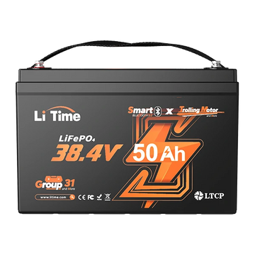
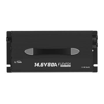
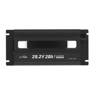
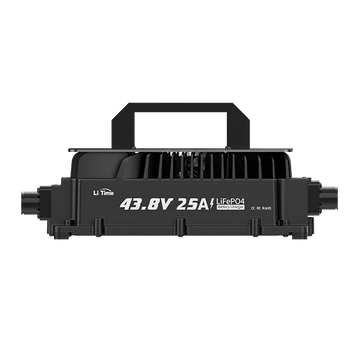
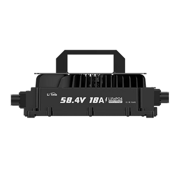
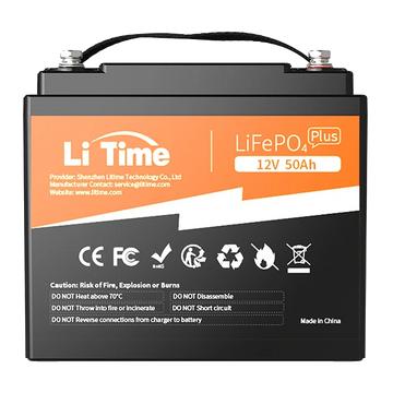
Some AGM/Gel algorithm lead-acid chargers may have a voltage range (14.0V~14.6V) that aligns with LiFePO4 charging requirements (12V systems recommend 14.4V). For different voltage LiFePO4 battery packs or systems, please refer to the table below:

However, the following conditions must be met:
- No repair/desulfation function – High-voltage pulses can trigger BMS protection or even damage battery cells.
- Voltage must match – The charger's maximum voltage must be ≤14.6V (12V system) and must not include a float charge phase (LiFePO4 does not require float charging).
- Disable voltage detection – If BMS disconnects due to low voltage (<10V), lead-acid chargers may detect “0V” and refuse to charge.
Risks of Long-Term Use
- Undercharging: Lead-acid chargers may not provide precise constant voltage (CV) control, leading to gradual capacity loss over time.
- Frequent BMS protection triggers: Voltage fluctuations or high-voltage absorption stages from lead-acid chargers may cause BMS disconnection, interrupting charging and leading to cell imbalance.
- Inability to wake up a “0V” battery: If the BMS disconnects due to over-discharge, lead-acid chargers may fail to detect the battery and refuse to charge, requiring a dedicated charger for activation.
When Should You Switch to a LiFePO4 Battery Charger?
- BMS frequently disconnects during charging.
- The battery fails to reach over 90% charge consistently.
- The charger has desulfation/repair functions or is labeled “for lead-acid batteries only.”
Why Is a Dedicated LiFePO4 Battery Charger the Better Choice?
1. Precisely Matches the CC/CV Charging Curve
Constant Current (CC) Phase
- The charger supplies a steady current, typically 0.5C-1C of the battery capacity (e.g., a 100Ah battery charges at 50A100A).
- This allows for fast charging, reaching 80% capacity within an hour.
- Voltage gradually increases—for a 12V system, voltage rises from 12.8V to 14.4V (matching 3.6V~3.65V per cell) before transitioning to constant voltage mode.
Constant Voltage (CV) Phase
- The charger maintains a precise voltage (e.g., 14.4V for a 12V system) to prevent overvoltage damage.
- Charging slows down naturally, and when current drops to 0.05C (e.g., 5A for a 100Ah battery), charging stops automatically to prevent overcharging.
Balancing & Charge Termination
- Cell balancing: The charger works with the BMS to equalize cell voltage, preventing overvoltage or undervoltage issues.
- Intelligent charge termination: Unlike lead-acid chargers that rely on fixed timing or simple voltage cutoffs, LiFePO4 chargers adapt dynamically to ensure a healthy charge cycle.
Comparison:
- Lead-acid chargers – May prematurely cut off charging or apply high-voltage absorption, leading to cell damage.
- LiFePO4 chargers – Precisely adjust current and voltage, ensuring optimal battery health.

2. Overcomes BMS Compatibility Issues
- Supports low-voltage wake-up – If BMS disconnects due to over-discharge, a dedicated charger can force activation and restore charging.
- Built-in temperature compensation (not voltage compensation) – Ensures reliable charging in -20°C~45°C environments (BMS must first deactivate low-temperature protection).
3. Extends Battery Lifespan
- Prevents float/trickle charging, reducing oxidation stress on battery cells.
- Accurate voltage control prevents overcharging, which can cause electrolyte breakdown or cell swelling.
Three Best Ways to Charging a LiFePO4 Battery
As mentioned in the preparation stage, there are three main charging LiFePO4 battery methods (charger/solar/generator). Below is a detailed breakdown of each, helping you choose the most suitable option based on your needs.
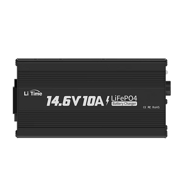
1. Dedicated LiFePO4 Battery Charger
Principle and Advantages
A dedicated charger is specifically designed for LiFePO4 batteries, following a Constant Current (CC) → Constant Voltage (CV) two-stage charging process:
- CC Stage: Charges at 0.5C~1C current (e.g., 100Ah battery uses 50A~100A), reaching 80% charge in about one hour.
- CV Stage: When the voltage reaches the set level (e.g., 14.4V for a 12V system), the charger automatically switches to constant voltage mode, gradually reducing the current to 0.05C before stopping to prevent overcharging.
Best Use Cases
- ✔ Home use or charging in fixed locations
- ✔ Users who need fast charging and battery health management
Important Notes
- Ensure the charger is explicitly labeled as LiFePO4-compatible to avoid issues like BMS overprotection when using a lead-acid charger.
- If the battery has triggered BMS protection due to over-discharge (0V display), use a dedicated charger with a "wake-up" function to restore charging.
The following video addresses common misconceptions about the LiFePO4 Battery Charger for your reference.
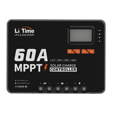
2. Solar System + MPPT Controller
Core Components and Functions
- Solar Panels: Power output should match the battery capacity (recommended daily generation ≥1.2x battery capacity).
- MPPT Controller: Tracks the solar panel's maximum power point, improving conversion efficiency by 20%-30% compared to PWM controllers.
- Parameter Settings: The controller must be configured for LiFePO4 charging voltage (e.g., 14.4V for a 12V system) and disable float charging mode (used in lead-acid batteries).
Best Use Cases
- ✔ Off-grid power supply, RVs, boats
- ✔ Long-term use in areas with abundant sunlight
Practical Tips
- Regularly clean the solar panel surface to reduce annual power loss by 5%-15%.
- Use a battery temperature sensor to prevent charging in extreme conditions (below -10°C or above 45°C).
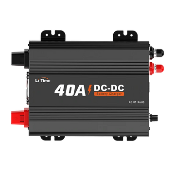
3. Vehicle Alternator + DC-DC Charger
How It Works
A vehicle alternator's output voltage fluctuates (12V-15V), which can damage the battery if connected directly. A DC-DC charger ensures:
- Voltage Regulation: Converts input voltage into a stable LiFePO4 charging voltage (e.g., 14.4V).
- Current Limiting: Adjusts charging current based on battery capacity (recommended 0.2C, e.g., 100Ah battery uses 20A).
Best Use Cases
- ✔ Charging LiFePO4 battery while driving in RVs or vans
- ✔ Emergency charging when no grid power is available
Key Considerations
- Choose a DC-DC charger with LiFePO4 mode (e.g., Kisae DMT1250).
- Connect the alternator to both the vehicle starter battery and the LiFePO4 battery to avoid disrupting the vehicle’s electrical system.
How Long Will It Take to Charge a LiFePO4 Battery?
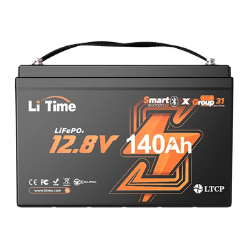
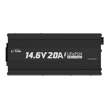
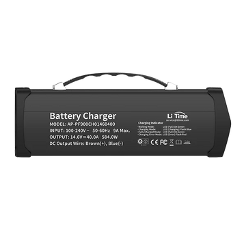
Charging Time Calculation & Real-World Data, Example: LiTime 12V 140Ah Battery
Using a LiTime 12V 140Ah Bluetooth LiFePO4 Battery with a LiTime 12V(14.6V) 20A LiFePO4 Battery Charger as an example:
1. Theoretical Charging Time
- Battery Capacity: 140Ah
- Charging Current: 20A (0.14C rate, lower than the recommended 0.2C for longer battery lifespan)
- Formula: Charging time ≈ Capacity ÷ Charging current × Efficiency factor (90%)
- Result: 140Ah ÷ 20A × 1.1 ≈ 7.7 hours (Actual time is around 7-8 hours, accounting for current tapering in the CV stage).
2. Real-World Variations
- Charging from 20% SOC (28Ah used): Requires 112Ah replenishment, taking about 6.2 hours.
- Cold temperatures (<5°C): BMS may limit charging current, increasing charge time by 10%-20%.
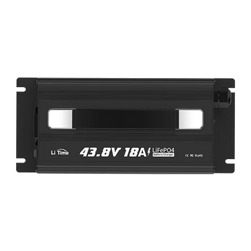
Why Choose the LiTime 14.6V 20A Charger?
1. Optimized for LiTime Battery Performance
- Precise voltage output (14.6V) ensures compatibility with LiTime battery BMS thresholds (3.2V × 4 cells), avoiding overvoltage protection triggers.
- 20A current balances efficiency and safety, with a 0.14C rate reducing cell heating and extending cycle life.
2. Activation & Protection Features
- "Sleep Mode Wake-Up" support: If the battery shuts down due to over-discharge (0V BMS cutoff), the charger can force activation.
- Built-in temperature sensor interface: Automatically pauses charging below 32°F (0°C) to protect the battery and resumes at 41°F (5°C).
Key Advantages of the LiTime 12V 140Ah Battery

1. High Efficiency & Lightweight Design
- 1792Wh capacity, weighing only 28.02 lbs, saving 140% more space compared to a 28V 12Ah lead-acid battery.
- 150A continuous discharge (700A peak @1s), easily powers RV appliances, coffee makers, A/C units, and 30–70 lb trolling motors.
2. Advanced Safety Features
- IP65-rated protection: Dustproof & water-resistant, suitable for marine, RV, and off-road environments.
- Cold-weather performance: Low-temperature cutoff protection for reliable operation in Canadian climates.
- Bluetooth monitoring: Real-time SOC, voltage, and temperature tracking via the app.
3. Durability & Compatibility
- Group 31 standard size (13 × 6.77 × 8.5 in), fitting 99% of RV battery compartments with no modifications required.
Here are the real-world test results of the LiTime 12V 140Ah Bluetooth LiFePO4 Battery in actual applications:
FAQs on charging lifepo4 batteries
How to Charge Parallel LiFePO4 Batteries
Key Principle:
Total charging current ≤ Maximum allowed current per battery module
Example: Two 12.8V 100Ah batteries in parallel
Maximum charging current per battery: 25A (0.25C) (LiTime batteries typically support up to 1C charge/discharge, but 0.25C is recommended for longer lifespan).
Recommended total charging current: ≤50A (not 100A)
Reason:
If charging at 100A, the first battery to reach full charge will trigger voltage protection and disconnect, causing the entire remaining current to flow into the second battery, leading to overcurrent protection and shutdown, leaving both batteries uncharged.
Limiting the total charging current to ≤50A ensures that if one battery disconnects, the other can still charge safely.
Important Notes:
Use a busbar for connections to prevent battery terminals from melting due to high current flow.
Voltage difference between parallel batteries should be <0.1V, and internal resistance difference <5%.
For discharging, follow the same principle: Total load current ≤ Maximum discharge current per battery module.
How to Charge Series LiFePO4 Batteries
Key Principle:
Charging voltage must match total system voltage, and current ≤ individual battery limits
Example: Two 12.8V 100Ah batteries in series (25.6V system)
Charger requirements: 29.2V output voltage, current ≤25A (0.25C).
Important Notes:
Battery consistency: Series batteries must have matching capacity and internal resistance (<3% difference); otherwise, one cell may overcharge and trigger BMS protection.
Disable low-voltage wake-up: If a single cell enters sleep mode due to over-discharge, the total voltage may still be above the charger’s activation threshold, requiring individual activation.
Key Considerations When Connecting LiFePO4 Batteries in Series or Parallel
1. Pre-charge before connection:
Before connecting, fully charge each battery separately and let them rest for 12-24 hours.
If voltage differences exist, parallel connections may cause high inrush current, damaging the battery, while series connections may lead to significant capacity reduction.
2. Use batteries of the same batch:
Avoid mixing new and old batteries, different capacities, or batteries with different cycle counts.
Mismatched batteries can cause overcharging in higher-capacity batteries and over-discharging in lower-capacity batteries.
3. Ensure consistent wiring:
Use identical cables that can handle the maximum expected current.
Insufficient wiring capacity can lead to overheating and fire hazards.
4. Monitor battery voltage monthly:
If the voltage difference exceeds 0.2V, disconnect the batteries and rebalance before reconnecting.
5. Check terminal connections regularly:
Prevent oxidation or loose connections, which can increase contact resistance and cause inefficiencies.
6. Install a fuse in the main circuit:
The fuse should be rated at ~1.5x the maximum charge/discharge power for added protection.